Optical Delay Line (ODL): Enhancing Signal Accuracy

Optical Delay Line (ODL): Enhancing Signal Accuracy
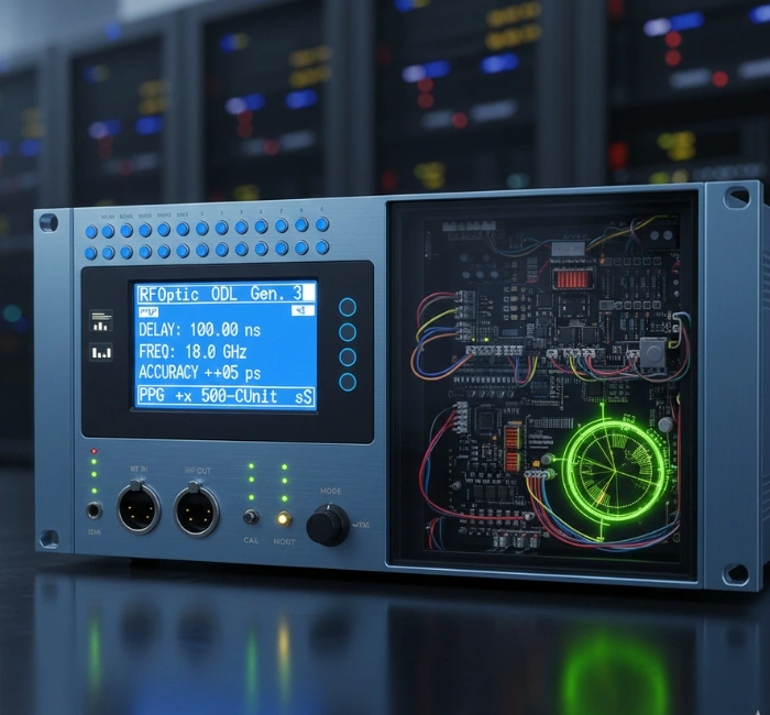
In the rapidly evolving world of advanced signal systems, especially in aerospace, defence, and high‑end communications, the ability to introduce precise, controllable delay into radio‑frequency paths is crucial. The latest generation of the RFOptic optical delay line (ODL) 🔗 family offers a compelling solution for applications ranging from radar calibration to RF communications and electronic warfare. By converting RF signals to optical form, delaying them via fibre or internal switching, and returning them to electrical form, the ODL enables signal timing and phase control with very high accuracy.
Overview
The optical delay line (ODL) is designed for use in demanding systems, such as radar testing, remote‑antenna calibration, and EW (electronic warfare) environments, where signal fidelity, delay accuracy, and frequency coverage are paramount. It supports high‑frequency bands (up to 40GHz) and can provide fixed or progressive delay values, making it suitable for both static system setups and dynamic, programmable applications.
In short, this is not a generic delay box; it is a purpose‑built product family for high‑end RF and fibre‑optic signal path applications.
Key features and benefits at a glance:
- Frequency range up to ~40GHz, covering K‑ and Ka‑bands and beyond.
- Delay ranges from very short (nanoseconds) up to hundreds of microseconds (with customised longer delays).
- Excellent delay accuracy and repeatability (e.g., <1% accuracy for delays >1µs; repeatability <0.01% under ±5°C).
- Progressive‑delay (multi‑state) or fixed‑delay configurations, giving versatile system architecture options.
- Remote control and monitoring, including front‑panel, USB, Ethernet/REST options.
- Applications in radar altimeter testing, EW & radar calibration, telecomms channel simulation, and remote antenna delays.
Why Delay Matters in RF/EW Systems
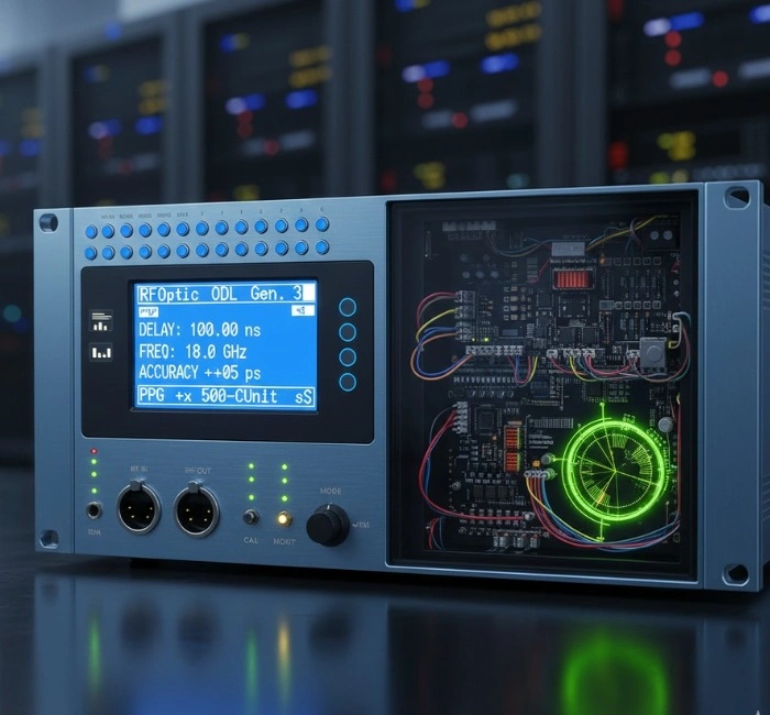
In high‑performance systems, especially in the field of RF electronic warfare (EW) solutions 🔗, the precision of signal timing, phase alignment, and channel delay modelling can make or break system behaviour. The optical delay line (ODL) enables one to emulate propagation delays, synchronise remote node signals, calibrate radar systems, or introduce measured time shifts so that system responses remain accurate.
When dealing with EW applications, jamming, deception, and surveillance, the ability to introduce consistent, repeatable delay helps ensure that the system under test sees the correct timeline of signals, preventing mis‑timing, which might otherwise degrade performance or introduce errors.
Additionally, the use of fibre‑optic delay means lower losses over long delays compared to pure electrical delay lines, better isolation from electromagnetic interference, and more flexible repositioning of components. The ODL enables signal fidelity to be maintained across wide frequency bands (including up to 40GHz), which is particularly important for modern EW and radar suites.
Product Architecture & Variants
The ODL product family addresses different frequency bands and system architectures:
- Low‑frequency ODLs: Up to ~6GHz, direct‑modulation architecture—for simpler, lower‑frequency applications.
- High‑frequency ODLs: Versions covering up to ~12GHz, ~18GHz, ~20GHz, ~27GHz, and up to 40GHz upon request. These support indirect modulation (L, S, C, X, Ku, K, and Ka bands) for high‑end radar/EW systems.
- Delay configuration options: Fixed single‑delay lines, offset/spool‑based fibre delays, or progressive/programmable delay banks (e.g., 2ⁿ states, up to 4,096 steps) for flexible delay modelling.
- Control and integration: The units support front‑panel or remote control (USB, Ethernet, REST API). They can integrate into automated test benches or EW system simulation setups.
These architectures allow users to select the most appropriate variant for their system: e.g., a radar altimeter test rig may only need moderate frequency coverage and a fixed delay; an EW simulation setup may need variable delays, high frequency coverage, and remote control.
Applications & Industry Use
Radar calibration & testing: The optical delay line can replica propagation delays or simulate target return times for radar altimeter testing, enabling accurate calibration of radar systems.
Electronic warfare & defence systems: For RF EW solutions, the ODL enables delay insertion, signal phasing, clutter cancellation simulation, and jamming channel modelling. Its high dynamic range and wideband coverage support these demanding use cases.
Telecommunications & remote antenna links: The ODL can simulate channel delays, manage remote antenna timing skew, or test distributed systems in 5G, DAS, or satellite links. The fibre‑based architecture provides low‑loss delay over long lengths and stable phase behaviour. 🔗
In short: if your system requires high‑precision delay control in RF‑over‑fibre, the optical delay line is a key enabling component.
Technical Highlights & Performance Metrics
According to manufacturer data:
- Frequency range: from approx. 0.1GHz up to 40GHz (and beyond upon request), depending on variant.
- Delay range: 0.1µs up to hundreds of microseconds (some up to 700µs or more) depending on customer configuration.
- Delay accuracy: typically <1% for delays above 1µs; minimum accuracy down to 0.1% in some cases.
- Repeatability: less than 0.01% over ±5°C temperature variation.
- Delay steps (in progressive mode): up to 4,096 or more selectable delay states.
- Switching time: as low as 100µs for special request units; standard units under 10ms.
These performance metrics underscore how the product is designed for precision, reliability, and flexibility, key attributes for high‑end environments such as RF electronic warfare 🔗 solutions and advanced radar systems.
Benefits & Why Choose This ODL
- High‑Frequency Coverage: Up to 40GHz means you’re prepared for modern radar bands and EW signal bands.
- Precision Delay Control: Accurate delay insertion ensures system timing and phase coherence, reducing errors in calibration or simulation.
- Programmable Flexibility: Progressive delay options allow dynamic changes in delay state, valuable for simulation or variable conditions.
- Remote/Automated Control: USB/Ethernet/REST interface enables integration into automated test benches or remote deployments.
- Low‑Loss Delay Over Fibre: By converting RF to optical, transmitting, and converting back, the architecture retains signal integrity over longer delays.
- Tailored to EW & Defence: With specific mention of EW, radar altimeter test, and remote antenna applications, it is clearly suited for mission‑critical environments.
Considerations & Best Practices
When integrating an optical delay line (ODL) into your system, keep in mind:
- Specify the frequency band carefully: different variants cover up to 12GHz, 18GHz, 20GHz, 27GHz, or up to 40GHz. Ensure the variant matches your system’s upper frequency.
- Decide on fixed vs progressive delay: Fixed delays are simpler; progressive (multi‑state) delays enable advanced simulation but may cost more or require additional control logic.
- Consider delay range and step resolution: If you need very long delay times or very fine steps, ensure the chosen unit supports them (some models support up to 700µs+).
- Ensure control interface compatibility: For automated test rigs, verify remote control via USB/Ethernet/REST is available.
- Environment and temperature: While repeatability is strong, high‑performance systems should consider calibration and monitoring if temperature swings are large.
Summary
For organisations working with high‑frequency radar systems, remote antenna links, EW simulators, or advanced RF communications testbeds, the optical delay line (ODL) from RFOptic offers a compelling solution. With frequency coverage up to 40GHz, delay precision, remote programmability, and fibre‑optics advantages, it addresses many of the timing and signal‑fidelity challenges in modern high‑end systems. If your next programme requires accurate, controllable delay insertion in an RF over fibre path, this ODL product family deserves serious consideration.
Frequently Asked Questions (FAQs)
Q1: What frequency bands does the optical delay line support?
A1: The ODL supports frequency ranges from about 0.1GHz up to 40GHz, depending on variant, covering L, S, C, X, Ku, K, and Ka bands. 🔗
Q2: Can the delay be programmed or varied dynamically?
A2: Yes. Some models offer progressive delay banks with multiple selectable states (e.g., up to 4,096 steps) and controlled switching times (standard under 10ms; special under 100µs) via remote interface. 🔗
Q3: What delay range and accuracy can I expect?
A3: Typical delay ranges span from nanoseconds to hundreds of microseconds (e.g., 0.1µs to ~700µs or more on request). Accuracy is typically <1% for delays above 1µs, with repeatability <0.01% under temperature variation. 🔗
Q4: Is the optical delay line suitable for RF electronic warfare (EW) solutions?
A4: Absolutely. The product family is explicitly designed for applications such as EW & radar, remote antenna calibration, altimeter test, and simulation of delay paths, making it very suitable for RF electronic warfare (EW) solutions.

Login to comment.
No thots yet. Be the first to share your thoughts!